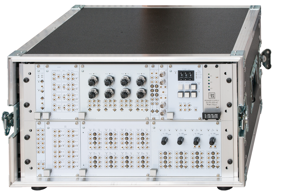
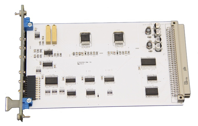
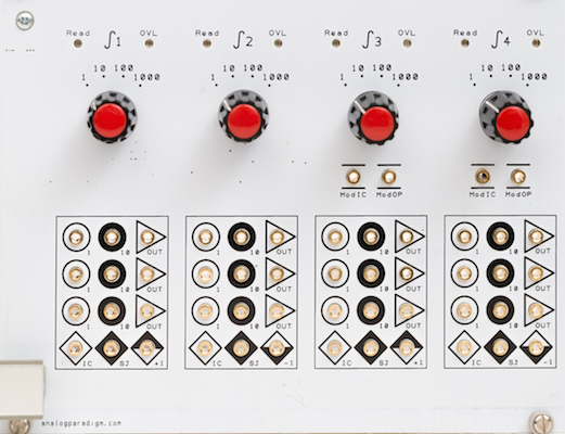
The "Analog Paradigm Model-1" analog computer shown above is a modular analog computer ideally suited for schools, universities and research institutes. Due to the modular approach systems can be configured according to customer requirements. The computer shown above is a minimum system consisting of two 19-inch industry standard chassis. It can be expanded to up to four chassis each holding a freely configurable complement of computing elements which will be described in the following. All modules are based on modern integrated circuits delivering a large range of functionality in a small volume with low overall power consumption. The two pictures below show two typical modules. On the left is the so-called PS-module which derives the highly stable machine units of +/-10 V and contains the necessary elements to detect over-/undervoltages and overload situations. The picture on the right shows the back of the INT4-module which contains four integrators, each having four time constants 1, 10, 100, and 1000 for high-speed computations. |
||
|
|
|
| ||
|
As of January 2017 the following modules are available: |
||
| ||
|
|
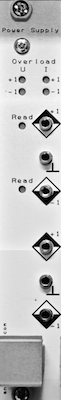
The PS-module derives the highly stabilized +/-10 V which are called "machine units" as all computations are based on these two values which are treated as +/-1 during programming of the machine. Although these two voltages are available on the front panels of other computing modules as well (PT8, INT4), they are also available at the front of the PS-module. The four overload LEDs are lit when either the output voltage is out of bounds or if the external load is too high (which is normally caused by patching errors). |
| ||
|
|
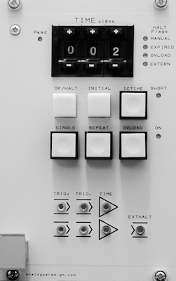
The CU-module (short for "Control Unit") is the heart of the analog computer as it controls the overall operation of the computer. It is possible to control the three modes of operation ("IC" - initial condition, "OP" - operate, and "HLT" - halt) manually or to have the computer perform a computation repeatedly with the OP-time controlled in 20 ms increments as set by the three digit switch on top of the module. Using repetitive operation it is possible to generate standing (often even flickerfree) pictures on an oscilloscope (in the picture on the left, an OP time of 20 ms has been setup). Pressing the IC switch selects the IC mode: All integrators assume their initial condition, preparing them for a computation which is initiated by pressing the OP/HALT button once. Pressing this button a second time causes the computer to go into HLT mode where the integrators hold their last output value. Depending on the time constants set at the integrators, the time necessary to load their respective initial conditions varies. Using the ICTIME button the IC time can either be set to long (sufficient for integrators set to time constant 1 or 10) or fast (about 10 ms) (for computer setups employing only integrators set to a time constant of 100 or even 1000). By pressing the OVLOAD button the CU is setup to halt the current OP cycle if an overload occurs at any computer element of the computer. Pressing the SINGLE button once will cause the computer to run through IC mode, followed by one OP cycle (the duration of which is controlled by the dial on top of the module), followed by HLT. Pressing the REPEAT button causes the computer to switch repeatedly into IC and OP mode. Four output jacks yielding a trigger signal which denotes an OP cycle are available as well as two output jacks where a voltage proportional to the duration of the OP cycle is available. The EXTHALT input makes it possible to halt an OP cycle by external means such as a comparator etc. |
| ||
|
|
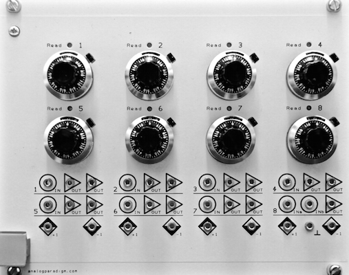
The PT8-module contains eight precision potentiometers, one of which (number eight) can be used as a so-called "free potentiometer" as both of its inputs are available at the front while the other seven potentiometers act as pure coefficient potentiometers with one input each. If potentiometer eight is to be used as such a coefficient potentiometer, its INb input must be connected to the ground jack below. Also available on front panel jacks are the machine units which simplifies patching constants which may be used as initial conditions for integrators. |
| ||
|
|
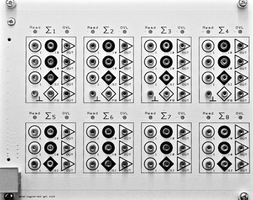
The module SUM8 contains eight summers which are grouped into two groups of four summers each. The four summers at the bottom each have three inputs weighed with 1, and two inputs weighed with 10. In addition to that the summing junction is also available. This is useful either to extend the input capabilities by additional resistive input networks (XIR-module, see below), or for additional feedback elements like diodes to limit the output value etc. The four summers in the top row can be configured as so-called "free amplifiers" by disabling their internal feedback path. This is done by patching the FB jack to a ground jack. Such free amplifiers are used to implement implicitly defined functions like a division or square root based on a multiplier in the feedback path. |
| ||
|
|
The INT4-module contains four integrators, each offering four time constants (1, 10, 100, and 1000). Each integrator has six inputs, three of which are weighed with 1 while the other three have a weight of 10. The jack denoted by IC is used to feed an input condition to the integrator while the SJ jack allows access to the summing junction of the operational amplifier and can be used to connect additional networks into the feedback loop of the integrator such as diodes to limit its output value etc. The SJ input may also be used to extend the input capabilities by connecting passive resistor networks such as those contained in the XIR-module (see below). The two right-most integrators have to additional jack each, labeled ModIC und ModOP. Using these inputs it is possible to override the central control signals generated by the CU by applying external control signals. This is often useful when two or more groups of individually controlled integrators are required (e.g. in optimization problems). |
| ||
|
|
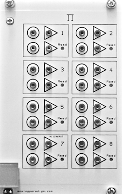
The MLT8-module contains eight identical multipliers. (If division or square rooting are required in a particular setup, this is normally implemented either by means of a free amplifier as an implicit function or by the MDS2 module described below.) |
| ||
|
|
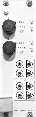
The module MDS2 contains two computing elements which can be switch selected to act as either multipliers, dividers or square root circuits. This module has only half the width of the MLT8 module and saves one free amplifier for each division/square rooting. |
| ||
|
|
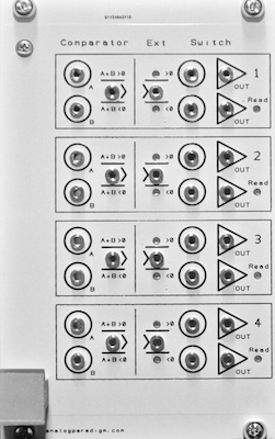
The CMP4-module contains four comparators which yield a logical output signal which is high when the sum of both analog inputs is larger than zero. Otherwise the output is low. Each comparator has a dedicated electronic SPDT switch with two analog inputs and one analog output. If the control input jack of such a switch remains unpatched, it is automatically connected to its corresponding comparator. By patching a control signal to an input this internal connection is split and the switch can be controlled externally. Thus only a single patch cable is necessary to control two switches by the output of one comparator. |
| ||
|
|
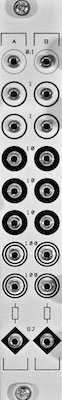
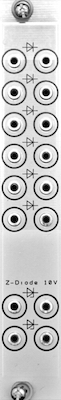
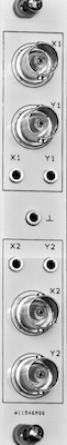
In addition to these active computing modules, there are three passive modules, named XIR, XID, and XIBNC as shown on the left (left to right). The XIR-module contains two precision resistor networks which can be connected to the SJ input of either a summer or integrator to extend the input capabilities of that particular element. The XID-module contains six free diodes as well as two 10 V Zener diodes which can be used to implement special non-linear functions such as output value limiter, absolute value, hysteresis etc. The XIBNC-module contains four standard BNC-jacks which are connected to a 2 mm jack as used throughout the Analog Paradigm analog computer modules. This module simplifies the connection of external devices such as oscilloscopes, signal generators etc. |
| ||
|
Using these modules and the Analog Paradigm bus system, it is possible to freely configure analog computers. Currently systems consisting of two to four chassis are supported although larger systems can also be built upon request. The only restriction is that a system always requires a power supply-module (not described above), one PS-, and one CU-module. A typical small system consists of
A large system consisting of five chassis (one prototype chassis on top and four chassis featuring the Analog Paradigm bus system) is shown below. This machine is programmed to compute the airflow around a Joukowski airfoil (see Application Note No. 4). 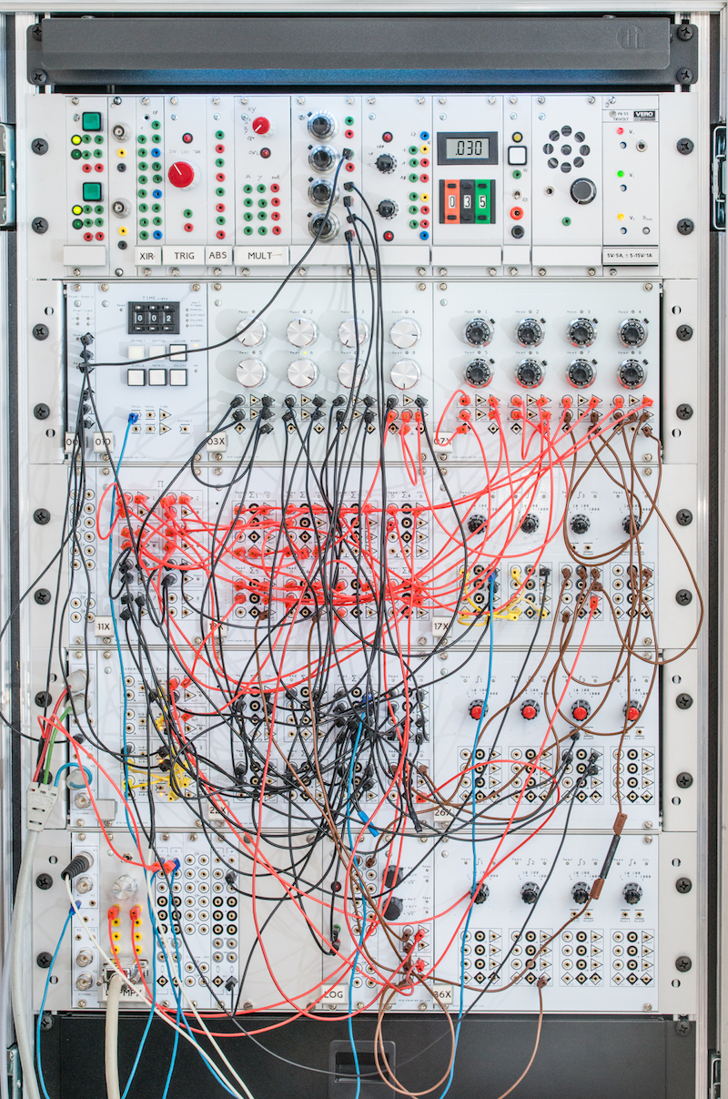
|
||